 Message
 中文
中文
 English

News


News
Understanding the Roles of 3-Pin M8 Waterproof Connector Terminals
Release time:2025-04-22
viewed:988
3-pin M8 waterproof connectors are compact, durable solutions for electrical connections in harsh environments, such as industrial automation, outdoor equipment, and sensor systems. While their small size and rugged design make them ideal for space-constrained or moisture-prone applications, understanding the function of each pin is critical for proper installation and performance. In this article, we’ll break down the roles of the three terminals and explain how they work together to ensure reliable connectivity.

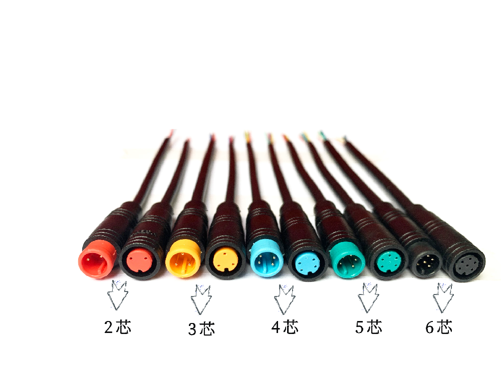
A standard 3-pin M8 connector consists of:
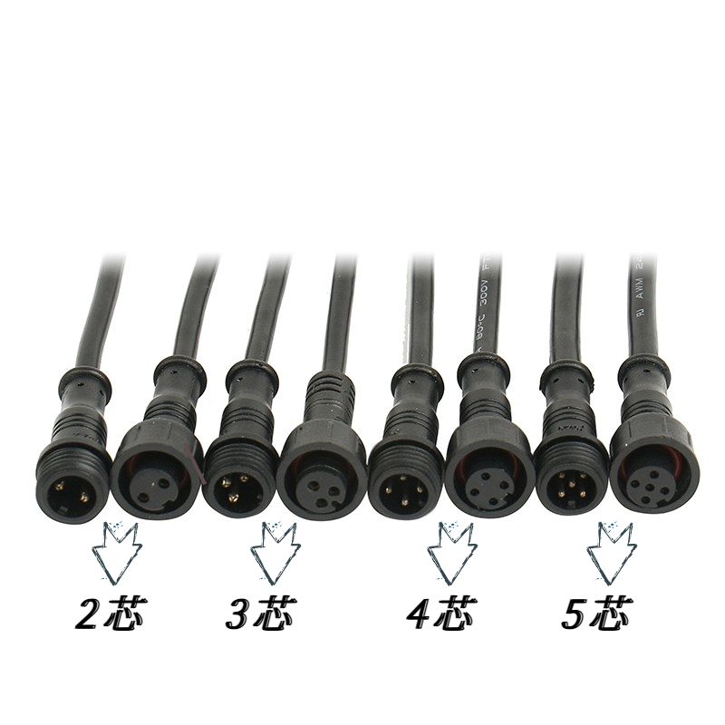
Male (Plug): Contains three metal pins housed in a threaded, waterproof enclosure.
Female (Socket): Features corresponding receptacles to accept the male pins.
Seals: Rubber O-rings or gaskets to prevent water ingress.
Locking Mechanism: A threaded coupling nut for secure mating.
The pins are typically labeled as Pin 1, Pin 2, and Pin 3, though their functions vary depending on the application.
The roles of the pins depend on the device or system they’re designed for. Below are the most common configurations:
This setup is widely used in sensors and low-power devices:
Pin 1 (Power Supply, V+): Delivers voltage to the connected device (e.g., 12V or 24V DC).
Pin 2 (Signal Output): Transmits data or feedback signals (e.g., analog 0–10V, digital PWM, or serial communication).
Pin 3 (Ground, V-): Completes the circuit and provides a return path for current.
Example: In a photoelectric sensor, Pin 1 powers the sensor, Pin 2 sends a detection signal to a controller, and Pin 3 grounds the connection.
In rare cases, 3-pin M8 connectors are used for low-current three-phase AC systems:
Pin 1 (Phase 1, L1): Carries the first phase of alternating current.
Pin 2 (Phase 2, L2): Carries the second phase.
Pin 3 (Phase 3, L3): Carries the third phase.
Note: This configuration is uncommon for M8 connectors, as three-phase systems typically require higher current ratings than M8 connectors provide.
Some industrial applications use shielded cables to reduce electromagnetic interference (EMI):
Pin 1 (Positive Power, V+): Supplies power.
Pin 2 (Negative Power, V-): Returns current.
Pin 3 (Shield/Drain): Connects to the cable’s shielding to divert EMI away from sensitive signals.
Example: In motor encoders, the shield pin protects signal integrity from nearby motors or inverters.

There’s no universal standard for 3-pin M8 terminal functions. Always refer to the device’s datasheet or connector pinout diagram to avoid miswiring, which can damage equipment or cause malfunctions.
Each pin has a maximum voltage and current rating. Exceeding these limits can lead to overheating or arcing. For example:
Standard M8 pins handle up to 30V and 4A.
High-performance variants may support higher ratings.
Even with correctly assigned pins, water ingress can occur if seals are damaged. Ensure:
O-rings are lubricated and free of debris.
The coupling nut is tightened to the manufacturer’s torque specification.
Cables are strain-relieved to prevent tugging on the pins.
These connectors are popular in:
Industrial Sensors (proximity, temperature, pressure).
Robotics (motor feedback, limit switches).
Outdoor LED Lighting (low-voltage power and control).
Automotive (sensors in engines or electric vehicles).
In a 3-pin M8 waterproof connector, each terminal plays a specific role—whether delivering power, transmitting signals, or grounding the system. Understanding these functions and adhering to manufacturer guidelines ensures optimal performance in demanding environments. By selecting the right configuration and maintaining the connector properly, you can extend the lifespan of your equipment and minimize downtime.
 Returns a list
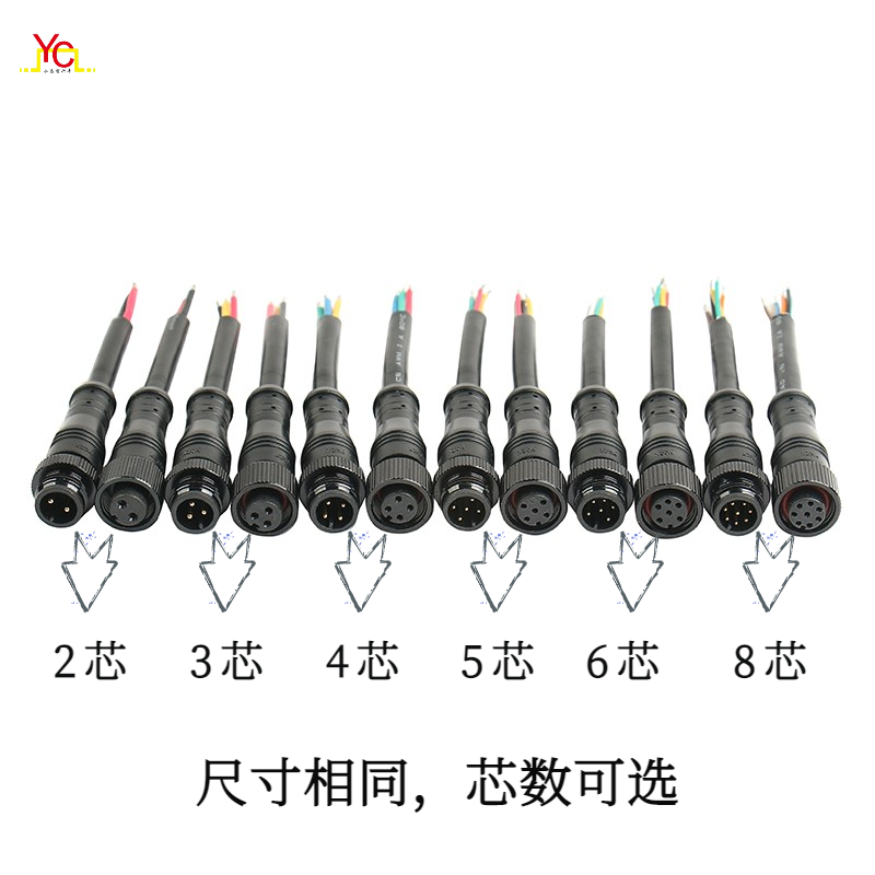
 0755-28471633